Leave Your Message
Why Choose a Motor Reducer for Industrial Applications?
Industrial equipment must deliver controlled torque, steady speed, and dependable operation under demanding conditions. A Motor Reducer combines an electric motor with a gearbox, reducing rotational speed while increasing usable torque. This arrangement supports conveyors, mixers, packaging lines, hoists, and automated production cells. The result is often a smaller, more controllable drive package. However, the choice should follow application data, not habit.
Energy performance makes this decision important. The International Energy Agency reported that electric motor-driven systems accounted for approximately 46% of global electricity consumption in its Energy-Efficiency Policy Opportunities for Electric Motor-Driven Systems report. The European Commission’s Motor Challenge Programme also estimated that motor systems could represent about 65% of industrial electricity use. These figures show where efficiency improvements may matter. Correct sizing can reduce wasted power, heat, and unnecessary mechanical stress. Small details matter. A lightly loaded reducer may operate inefficiently, while an undersized unit may overheat during peak demand.
A practical evaluation should examine output torque, duty cycle, speed ratio, shock loads, mounting position, lubrication, and service conditions. Engineers should also compare efficiency ratings, sealing protection, noise levels, maintenance access, and expected operating life. The U.S. Department of Energy’s Motor Systems Market Assessment emphasizes system-level analysis rather than isolated component selection. That assumption needs testing. A Motor Reducer is not automatically the best solution for every machine. Yet, when properly matched, it can simplify transmission design, stabilize production, and improve long-term reliability. Performance records from comparable equipment remain valuable evidence before final approval.
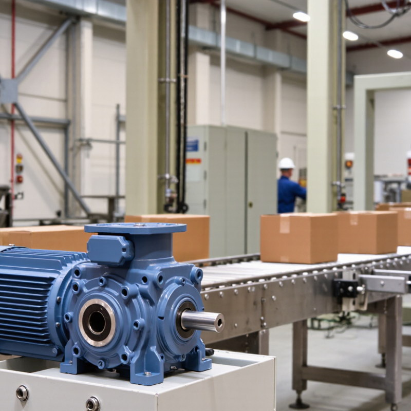
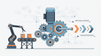
A motor reducer combines a motor with gears to deliver slower, stronger, and more controlled rotation. Gear ratio is the central design choice. A 20:1 reducer turns a 1,450 rpm motor into roughly 72.5 rpm. It also multiplies torque. For example, a 1 kW motor produces about 6.6 Nm at 1,450 rpm. Ideally, a 20:1 reduction provides 132 Nm. With 90% efficiency, the practical output is closer to 119 Nm. Real machines are less tidy.
This matters on conveyors, mixers, hoists, and packaging lines, where starting loads can exceed running loads. The International Energy Agency estimates motor-driven systems consume about 53% of global electricity. The U.S. Department of Energy also reports that motor systems can represent more than half of industrial electricity use. Choosing the correct ratio can reduce oversizing, heat, and wasted energy, but excessive reduction may limit speed and create poor dynamic response.
IEC ratings add another layer. IEC 60034-30-1 defines motor efficiency classes, including IE3 and IE4. A higher class generally reduces electrical losses, especially during long operating hours. However, the motor rating alone does not guarantee system efficiency. Gear losses, lubrication, alignment, duty cycle, and inverter settings also matter. Check rated torque, service factor, ambient temperature, insulation class, and IP protection before approval. In field commissioning, engineers sometimes focus on the nameplate and overlook peak torque. That is an avoidable mistake. A reducer should be selected from measured load behavior, not optimistic calculations.
| Selection Dimension | Typical Industrial Data | What It Means | Practical Selection Consideration |
|---|---|---|---|
| Gear Ratio | 5:1 to 10:1 | The reducer lowers speed by approximately five to ten times while increasing available output torque. | Suitable for conveyors, mixers, feeders, and machinery requiring moderate speed reduction. |
| Gear Ratio | 15:1 to 30:1 | Provides substantial speed reduction and higher torque multiplication in a compact drive system. | Commonly considered for indexing equipment, lifting mechanisms, packaging lines, and material-handling systems. |
| Gear Ratio | 40:1 to 100:1 | Produces low output speed and high theoretical torque multiplication. | Useful for slow-moving applications, but efficiency, heat dissipation, backlash, and service factor require closer review. |
| Output Speed | 30 rpm at 50:1 | Based on a 1,500 rpm motor speed divided by a 50:1 reduction ratio. | Actual speed depends on motor slip, frequency, load, and the selected transmission configuration. |
| Output Speed | 60 rpm at 25:1 | Based on a 1,500 rpm motor speed divided by a 25:1 reduction ratio. | Choose the ratio according to the required machine speed rather than motor speed alone. |
| Torque Multiplication | Tout ≈ Tin × ratio × efficiency | Output torque is increased by the ratio, but friction and gear losses reduce the ideal result. | Always use the manufacturer’s rated output torque and apply an appropriate service factor. |
| Example Torque | Approximately 180 N·m | A 10 N·m motor torque, a 20:1 ratio, and 90% efficiency produce about 180 N·m at the output. | Calculation: 10 N·m × 20 × 0.90 = 180 N·m, excluding transient loads and service-factor requirements. |
| Typical Efficiency | 85% to 96% | Efficiency varies with gear technology, ratio, load, lubrication, operating temperature, and alignment. | Higher efficiency generally reduces heat generation and operating energy consumption. |
| Helical Gear Reducer | Typically 90% to 96% | Helical gearing provides smooth, quiet power transmission and good efficiency. | A strong general-purpose option for conveyors, pumps, fans, and continuous-duty machinery. |
| Worm Gear Reducer | Typically 50% to 90% | Efficiency depends strongly on the ratio, lead angle, lubrication, and operating conditions. | Offers compact right-angle transmission and may provide static holding characteristics at selected ratios, but backdrivability must be verified. |
| Bevel-Helical Reducer | Typically 90% to 96% | Combines efficient helical gearing with a right-angle output arrangement. | Well suited to heavy-duty conveyors and applications where space or shaft direction is limited. |
| Service Factor | Commonly 1.25 to 2.00 | Accounts for shock loads, starts per hour, duty cycle, operating time, and application severity. | Intermittent shock loading usually requires a higher service factor than smooth, uniform loading. |
| Continuous Duty | S1 duty | The motor operates at a constant load long enough to reach thermal equilibrium. | Confirm that both the motor and reducer are rated for the required continuous operating time. |
| Short-Time Duty | S2 duty | The motor operates for a specified short period and then remains stopped long enough to cool. | Use the declared operating duration and cooling interval when checking thermal capacity. |
| Intermittent Duty | S3 duty | The motor runs in repeated cycles with load periods and rest periods, without reaching thermal equilibrium. | Check starts per hour, cycle duration, load profile, and permissible motor temperature rise. |
| IEC Motor Frame | IEC 63 to IEC 180 | IEC frame size defines standardized mounting and shaft dimensions within the relevant motor series. | Frame size alone does not define the motor’s complete power rating; speed, design, cooling, and duty must also be checked. |
| Common IEC Mounting | B3, B5, B14, B35 | B3 generally indicates foot mounting, B5 flange mounting, B14 face mounting, and B35 combined foot-and-flange mounting. | Match the motor mounting arrangement with the reducer input interface and machine structure. |
| Ingress Protection | IP55 to IP66 | The first digit relates to protection against solid particles; the second relates to water protection. | IP55 is common for general industrial environments, while higher protection may be required for washdown or dusty areas. |
| Insulation System | Class F, often Class B temperature rise | Insulation class F permits a higher winding temperature limit than Class B, while the actual temperature rise may be limited below that class. | Lower operating temperature generally supports longer insulation life and improved reliability. |
| Operating Frequency | 50 Hz or 60 Hz | Motor synchronous speed changes with supply frequency and pole count. | When used with a variable frequency drive, verify motor cooling, minimum speed, maximum speed, and reducer input limits. |
| Thermal Management | Oil or grease lubrication | Lubricant reduces wear and removes heat from gear contact surfaces. | Use the specified lubricant type, viscosity, fill level, and maintenance interval for the installation position. |
| Backlash | Application-dependent | Backlash is the angular clearance between mating gear teeth and affects positioning accuracy. | Low-backlash gearing is preferred for precision positioning, while standard gearing is often adequate for conveyors and fans. |
| Shaft Arrangement | Parallel, coaxial, or right-angle | The reducer configuration determines the relationship between the input and output shafts. | Select the arrangement that minimizes space requirements, coupling complexity, and shaft-loading problems. |
| Main Benefits | Lower speed, higher torque, compact drive | A motor reducer adapts a high-speed motor to the lower speed and higher torque required by industrial machinery. | Evaluate total lifecycle cost, efficiency, maintenance access, noise, thermal capacity, and replacement availability. |