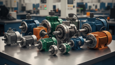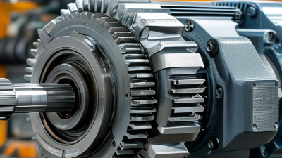
Choosing a Motor Reducer in 2026 is not a catalog exercise. It is a load-matching decision with consequences for energy use, uptime, and maintenance. The U.S. Department of Energy’s Improving Motor and Drive System Performance: A Sourcebook for Industry reports that motor-driven systems use about 68% of U.S. manufacturing electricity. That figure does not describe reducer losses alone, but it shows why the complete drive system deserves careful attention. Small mismatches add up.
A useful selection starts with the machine’s real operating conditions: required output torque, speed, duty cycle, start frequency, and ambient temperature. Picture a conveyor starting under a full load, or a mixer running through thick product. Both need more than a ratio copied from an old drawing. Check service factor, thermal capacity, mounting position, shaft loads, and lubrication requirements. Then compare efficiency, backlash, noise, enclosure rating, and expected maintenance access. A compact unit may save space. It may also run hotter.
Mechanical-design author Peter R. N. Childs’s published work offers a practical principle, paraphrased here: match the transmission to the actual load and duty cycle, not merely the headline ratio. That is a useful lens, not a substitute for calculations or supplier verification. Record assumptions, confirm peak and continuous torque separately, and request performance data for the intended operating point. If the application data is incomplete, say so. Guessing can look efficient on paper. It often isn’t in the plant.
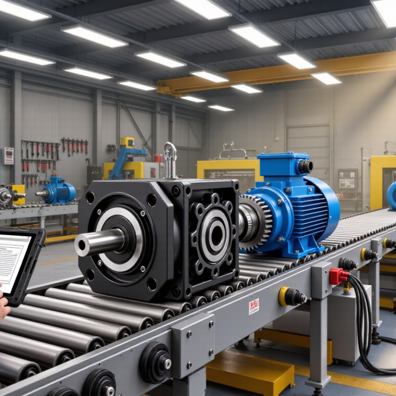
Before comparing motor reducers, define what the machine must do. Record the required output speed and torque, plus the load’s weight and movement pattern. A conveyor carrying steady boxes behaves differently from a mixer that starts with a full drum. Note how often the equipment starts, stops, reverses, or faces sudden impacts. These details affect reducer sizing and service life.
Operating conditions matter just as much. Measure the ambient temperature and check for dust, moisture, washdown, or limited airflow. A reducer inside a warm enclosure may need different lubrication or cooling than one in an open, clean room. Confirm the mounting position, available space, shaft orientation, and whether the unit must run quietly. Small constraints count. A shaft that misses its coupling by a few millimeters can create alignment problems.
Use measured values where possible, not just estimates from a product label. If the load varies, describe both its normal level and its peak demand. A common oversight is selecting for continuous torque while ignoring frequent starts. That can lead to heat buildup or premature wear. Even careful calculations have limits; real operating patterns are sometimes messier than a specification sheet suggests. Record assumptions, then verify them against the actual machine cycle before choosing a reducer.
How to Choose a Motor Reducer in 2026?
Calculate Required Output Torque, Speed, and Service Factor
Start with the load, not the catalog. Estimate required output torque from the force at the driven point multiplied by its distance from the shaft center. For a conveyor, include belt tension, product weight, friction, and acceleration. A 200-newton force acting on a 0.1-meter drum radius needs about 20 newton-meters before losses. Real machines rarely behave as neatly as a spreadsheet, so verify assumptions against actual operating conditions.
Tips: Calculate output speed from the required motion. For a wheel, use the desired travel speed and wheel circumference to find revolutions per minute. Then compare that speed with the motor’s rated speed to estimate the reduction ratio. Allow for reducer efficiency, and avoid choosing a ratio from speed alone.
Choose a service factor based on operating hours, starts per hour, and load shocks. A lightly loaded fan running steadily differs from a mixer that starts full and sees frequent torque spikes. Use the reducer manufacturer’s application guidance, and check both rated output torque and thermal limits. A higher service factor is not a substitute for accurate sizing. I would revisit the calculation after measuring the real load; that step is easy to skip, and it can expose a poor assumption.
How to read the chart: Calculated design torque = load torque × service factor. For each application, select a reducer whose rated output torque meets or exceeds the calculated value, then check peak torque and thermal capacity.
These are illustrative engineering examples, not universal service-factor recommendations. Choose the service factor based on the actual duty cycle, shock loading, starts per hour, and operating conditions. Approximate reducer output speed as motor speed ÷ reduction ratio; confirm the result using the motor’s actual operating speed.
How to Choose a Motor Reducer in 2026?
Compare Reducer Types, Ratios, and Efficiency
A motor reducer changes speed and torque, but its design affects heat, noise, and precision. Helical reducers usually run smoothly and efficiently in continuous-duty applications. Planetary reducers offer high torque in a compact package, though backlash and cost vary by design. Worm reducers can provide large reductions in a small space, but sliding contact may create more heat and reduce efficiency. Right-angle bevel reducers suit layouts where the motor and output shaft must meet at an angle.
The ratio links motor speed to output speed: a 20:1 reducer turns the output roughly once for every 20 motor revolutions. Output torque can rise with the ratio, but real gains depend on reducer efficiency and load. Higher ratios are not automatically better; they may slow the output too much or add heat. Small details matter. Check the required speed, starting torque, duty cycle, mounting position, and allowable backlash before choosing.
Efficiency should be compared at the expected load, speed, and temperature, not treated as a single guaranteed number. Lubrication, alignment, and operating hours can change performance. I would not rely on a catalog figure alone; it may assume ideal conditions. A practical test under load can reveal unexpected temperature rise or noise. Measure under load. Leave some capacity for real operating variation, while avoiding an oversized reducer that adds cost and inertia.
The ranges below are typical selection references, not guaranteed ratings. Actual performance depends on the reducer design, size, ratio, lubrication, input speed, load, and operating conditions. Confirm specifications with the manufacturer’s technical data.
| Reducer Type | Typical Ratio Range | Typical Efficiency | Backlash / Precision | Main Strengths | Typical Applications | Selection Considerations |
|---|---|---|---|---|---|---|
| Planetary | About 3:1–10:1 per stage; higher ratios with multiple stages | Often about 94–98% per stage | Low backlash options available; suited to precise motion | High torque density, compact coaxial layout, good load distribution | Robotics, automation, mobile equipment, servo drives | Check rated and peak torque, backlash class, duty cycle, and radial-load limits. |
| Helical | Commonly about 3:1–10:1 per stage; multiple stages provide higher ratios | Often about 94–98% per stage | Generally low to moderate; precision depends on design and grade | Efficient, smooth, and suitable for continuous operation | Conveyors, mixers, pumps, material-handling machinery | Allow for axial thrust from helical gears; verify mounting orientation and lubrication. |
| Worm | Commonly about 5:1–100:1 in a single stage | Broadly about 50–90%; often lower at high ratios | Typically moderate; backlash varies by construction and adjustment | Compact right-angle arrangement; high reduction in one stage | Gates, positioning equipment, compact right-angle drives | Consider heat and power loss. Do not assume self-locking; verify holding requirements separately. |
| Bevel-Helical | Often about 6:1–200:1 across available multi-stage configurations | Typically about 93–97% per stage | Generally low to moderate; depends on configuration and quality | Efficient right-angle power transmission and a broad ratio range | Industrial conveyors, process equipment, heavy-duty machinery | Check shaft arrangement, service factor, mounting position, and thermal capacity. |
| Cycloidal | Commonly about 6:1–119:1 per stage; higher ratios may use multiple stages | Often about 85–95%, depending on size and ratio | Low backlash designs available; good shock-load capability | High reduction in a compact package; tolerates intermittent shock loads | Robotics, indexing equipment, heavy-duty positioning systems | Review torsional stiffness, allowable moment loads, vibration, and maintenance needs. |
| Harmonic (Strain-Wave) | Commonly about 30:1–160:1 in a single stage | Often about 70–90%, depending on ratio and operating conditions | Very low backlash; high positional repeatability | High ratio and precision in a compact, coaxial package | Robot joints, optical equipment, precision positioning | Check rated torque, flexspline fatigue life, efficiency at the selected ratio, and shock limits. |
Start with the mounting arrangement, not the catalog photo. Confirm shaft direction, flange dimensions, foot spacing, and clearance against the machine drawing. A reducer may fit the frame but leave no room for a guard or service tool. Measure twice. Small details matter.
Match housing and gear materials to the actual environment. In a washdown area, corrosion-resistant surfaces and sealed joints may matter more than a polished finish. Dust, vibration, and outdoor temperature swings create different demands. Check the specified lubricant, mounting orientation, and service interval. Lubrication is not an afterthought. A wrong fill or missed interval can raise heat and wear, even when the load seems modest.
Assess the reducer, motor, and control system as one assembly. Compare output speed, torque, starting frequency, braking needs, and backlash with the real duty cycle, not just peak figures. With variable-speed control, verify cooling and low-speed torque behavior. Test under a representative load. Drawings rarely show every awkward cable bend, and tidy calculations can miss practical constraints. A little uncertainty deserves another check.
Evaluate Reliability, Lifecycle Cost, and Supplier Support
A reducer should match the real duty cycle, not just the motor’s rated power. Record load peaks, starts per hour, operating hours, and ambient temperature. Check whether the unit can handle shock loads and heat during continuous operation. Small details matter. In a packaging line, frequent stops may cause more stress than steady running. Ask for calculations based on your actual conditions, and review the assumptions behind them.
Purchase price is only one part of lifecycle cost. Include energy use, lubricant changes, inspection time, replacement parts, and the cost of unplanned downtime. Compare expected service intervals, but treat them as estimates. Dust, misalignment, and poor mounting can shorten them. A spreadsheet can make one option look clearly cheaper; that result may be wrong if maintenance labor or lost production is missing. Leave room for uncertainty.
Supplier support affects how quickly a problem gets resolved. Ask whether technical staff can review mounting drawings, explain service requirements, and help identify the cause of unusual noise or rising temperatures. Check spare-part availability and typical response times before ordering. Request clear documentation, including lubrication guidance and permitted operating limits. Then test the support process with a practical question. The answer, and how long it takes, can be revealing.